Sometimes you will need to work on separate views and project lines to each other to fully complete any view. 1 What type of sketch uses a miter line.
![]()
Orthographic Projection Multi View Drawing Ppt Video Online Download
Miter line is used to ensure the alignment of the three views.

. As per BIS the three views commonly shown on an orthographic drawing are top front and A. 13 Engineering Drawing MCQs and Answers Set-III. The section lines should be evenly spaced and of equal thickness and should be.
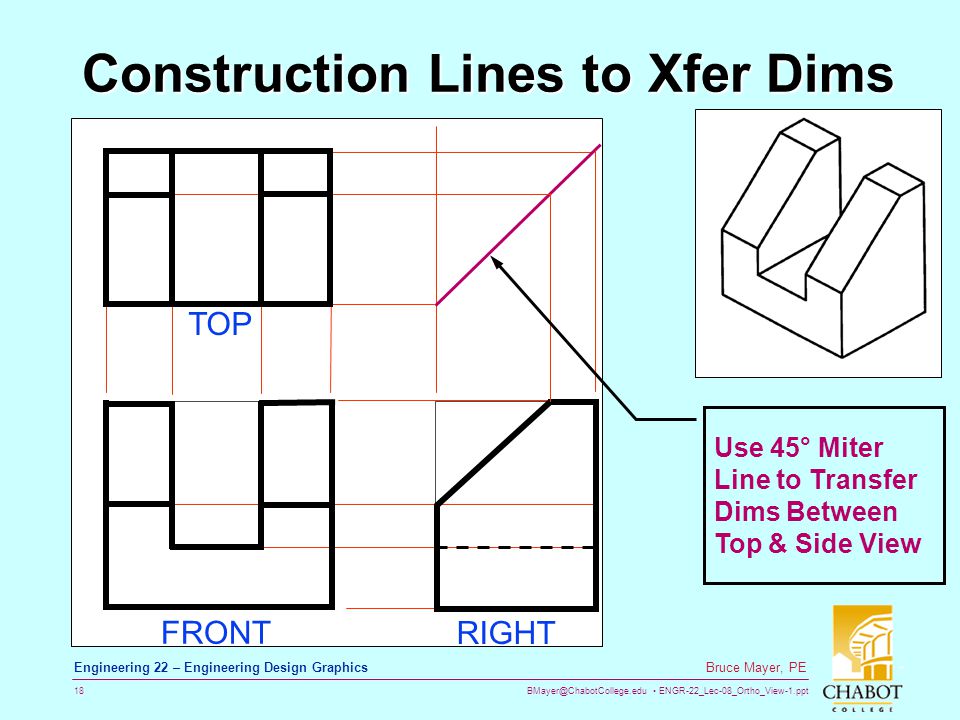
This preview shows page 10 - 12 out of 48 pages. A miter line is used to derive the depth dimension for the right side view from the top view. Figure 6 sh ows an example drawn in class.
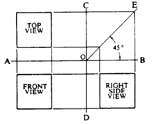
A miter line OE in the figure offers a convenient method of laying out a third view while you are in the process of drawing two views. On your own use the Offset and Trim commands and modify the top view as shown. Whatever area you will.
Visible Line Hidden Line Cutting-Plane Lines Center Line. Engineering Drawing WELCOME TO. However in a direct contradiction of this the standard ISO 128-24 1999 states that the thicknesses should be 025.
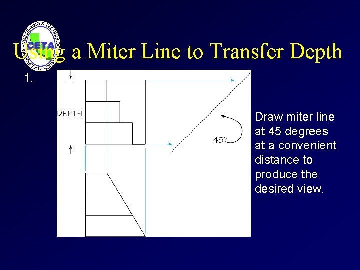
The Miter Line and Projection Lines The use of a 45 miter line and Projection Lines provide a quick accurate method of drawing the other views once one view is completed. Place the miter line OE to the right of the top view at a convenient distance keeping the appearance of a balanced drawing. Place the miter line OE to the right of the top view at a convenient distance keeping the appearance of a balanced drawing.
A miter line OE in the figure offers a convenient method of laying out a third view while you are in the process of drawing two views. Section lines are drawn as thin 35 mm black lines using an H or 2H pencil. 14 Engineering Drawing MCQs and Answers Set-IV.
As a general rule use 3mm spacing. Sometimes you will need to work on separate views and project lines to each other to fully complete any view. 15 Engineering Drawing MCQs and Answers Set-V.
The angle of a miter line is degrees A. 75 B 6B 2008. The angle of a miter line is degrees A.
Orthographic Views and Multiview Constructions 4-33 Drawing using the Miter Line method The 45 miter line method is a simple and straightforward procedure to transfer measurements between the top view and the side view. 16 Engineering Drawing MCQs and Answers Set-VI. None of these B 6B 2008.
Miter bend can be fabricated with 2 3 4 5 miters. Application size range can vary from company to company. Two widths of lines are typically used on drawings.
75 B 6B 2008. The thick line width should be 06 mm and the thin line width should be 03 mm. 11 Engineering Drawing MCQs and Answers Set-I.
Example Represent the shown component using multiple view representation. 12 Engineering Drawing MCQs and Answers Set-II. Draw light projection lines from the top view to the miter line.
What is a hidden line. Example Start with the front view The edge C cannot be seen but is. The standard ISO 128 1982 states that the thickness of the thick or wide line should be chosen according to the size and type of the drawing from the following range.
Drawing Techniques The general purpose cast iron section line is drawn at a 45-degree angle and spaced 15 mm to 3 mm or more depending on the size of the drawing. The numbers of cut will be a maximum of 5. The numbers of miters will be decided according to the pressure and temperature of the line.
A 6B 2008 99. The use of extension lines and miter lines is the purpose for the format taught earlier in this lesson. The other lines on the drawing.
A hidden line also known as a hidden object line is a. The Miter Line and Projection Lines The use of a 45 miter line and Projection Lines provide a quick accurate method of drawing the other views once one view is completed. Poor strength because of the more number of joints.
Limitations of Miter Bend. A miter line OE in the figure offers a convenient method of laying out a third view while you are in the process of drawing two views. As per BIS the three views commonly shown on an orthographic drawing are top front and A.
In technical Engineering drawings each line has a definite meaning and is drawn in accordance to the line conventions as illustrated in the figure below. A miter line is a 45 degree line draw between the top view and right side view by extending out a line on both view and connecting them. What is the role of a miter line in orthographic projection.
Place the miter line OE to the right of the top view at a convenient distance keeping the appearance of a balanced drawing.

How To Find The Side View Of A Point Mitre Line Arc Method Youtube

Orthographic Projection

Orthographic Projection
Orthographic Projection Multiview Drawing Orthographic Projection A System
Orthrographic View Dwgs 1 Ppt Video Online Download
2
![]()
Orthographic Projection Multi View Drawing Ppt Video Online Download
Using A Miter Line Manufacturinget Org
0 comments
Post a Comment